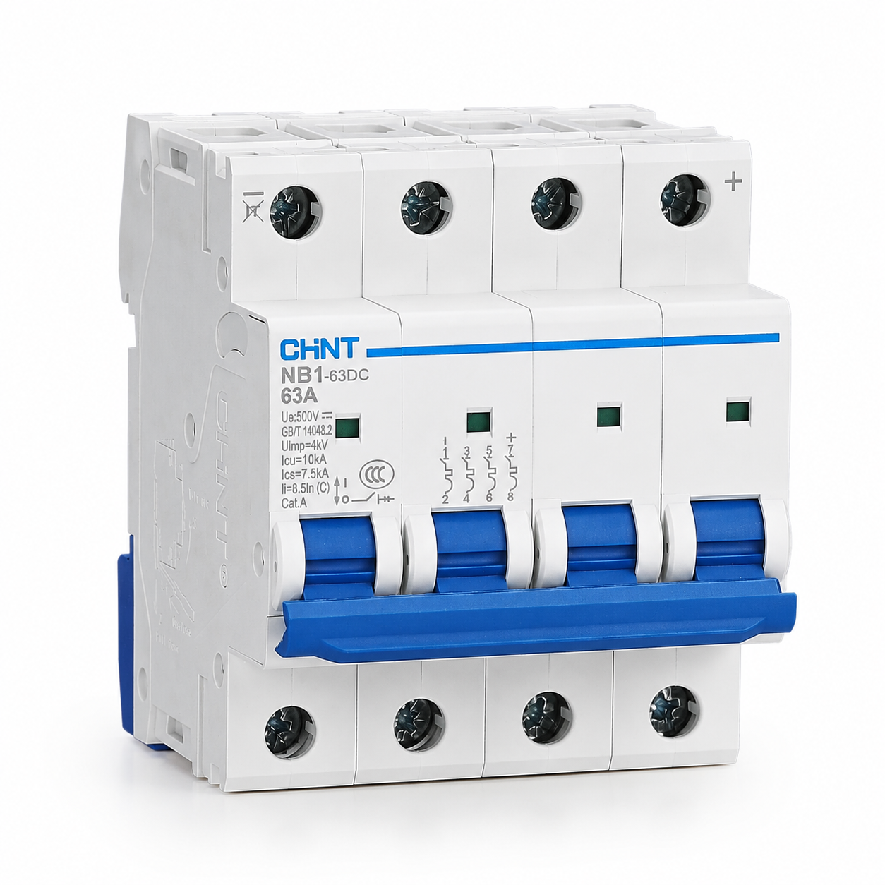
Function and Usage
NB1-63DC DC circuit breaker is used in DC rated voltage up to 1000V, rated current up to 63A circuits, to provide overload and short-circuit protection. It can be used for infrequent switching of the circuit under normal conditions. Complies with standards: GB/T 14048.2, IEC 60947-2, EU RoHS environmental requirements, and has obtained CCC, CE, EAC, TÜV certifications.
Detail Parameters
Main Parameter Table
Main Parameters and Technical Performance of Miniature Circuit Breaker
| Parameter Item | Parameter Value |
|---|
| Rated Voltage (Ue) | DC 125V/250V(1P), DC 250V/500V(2P), DC 500V/1000V(4P) |
| Rated Current (In) | 1A, 2A, 3A, 4A, 6A, 10A, 13A, 16A, 20A, 25A, 32A, 40A, 50A, 63A |
| Rated Insulation Voltage (Ui) | 1000V |
| Rated Impulse Withstand Voltage (Uimp) | 4kV |
| Poles | 1P, 2P, 4P |
| Instantaneous Trip Unit Type | C (7~10)In |
| Rated Ultimate Short-Circuit Breaking Capacity (Icu) | 6kA (1P 250V/2P 500V/4P 1000V); 10kA (1P 125V/2P 250V/4P 500V) |
| Overcurrent Protection Characteristics | See Table 2, Figure 1 |
| Mechanical and Electrical Life | Mechanical Life 20000 times, Electrical Life 4000 times |
| Current Correction Factor at Different Temperatures | See Table 3 |
| Current Correction Factor at Different Altitudes | See Table 4 |
| Connection Wires | See Table 5 |
| Tightening Torque | 2.0N·m |
| Power Consumption | See Table 6 |
| Wiring Diagram | See Figure 2 |
| Outline Installation Dimensions | See Figure 3, Figure 4 |
| Pollution Degree | Level 2 |
| Protection Level | IP20 |
| Installation Category | Class II, III |
Overcurrent Protection Characteristics Table
Overcurrent Protection Characteristics (Table 2)
| Serial Number | Test Current | Initial State | Time Limit for Tripping or Not Tripping | Expected Result | Notes |
|---|
| a | 1.05In | Cold state | t ≤ 1h | No tripping | - |
| b | 1.30In | Immediately after the previous test | t < 1h | Tripping | The current rises to the specified value within 5s |
| c | 7In | Cold state | t ≤ 0.2s | No tripping | - |
| d | 10In | Cold state | t < 0.2s | Tripping | - |
Temperature Current Correction Table
Current Correction Values at Different Ambient Temperatures (Table 3)
| Rated Current (A) | -35℃ | -30℃ | -20℃ | -10℃ | 1℃ | 10℃ | 20℃ | 30℃ | 40℃ | 50℃ | 60℃ |
|---|
| 1 | 1.3 | 1.26 | 1.23 | 1.19 | 1.15 | 1.11 | 1.05 | 1 | 0.96 | 0.93 | 0.88 |
| 2 | 2.6 | 2.52 | 2.46 | 2.38 | 2.28 | 2.2 | 2.08 | 2 | 1.92 | 1.86 | 1.76 |
| 3 | 3.9 | 3.78 | 3.69 | 3.57 | 3.42 | 3.3 | 3.12 | 3 | 2.88 | 2.79 | 2.64 |
| 4 | 5.2 | 5.04 | 4.92 | 4.76 | 4.56 | 4.4 | 4.16 | 4 | 3.84 | 3.72 | 3.52 |
| 6 | 7.8 | 7.56 | 7.38 | 7.14 | 6.84 | 6.6 | 6.24 | 6 | 5.76 | 5.64 | 5.28 |
| 10 | 13.2 | 12.6 | 12.3 | 12 | 11.4 | 11 | 10.4 | 10 | 9.6 | 9.3 | 8.8 |
| 13 | 17.16 | 16.5 | 16.25 | 15.6 | 14.95 | 14.43 | 13.78 | 13 | 12.48 | 12.09 | 11.57 |
| 16 | 21.12 | 20.48 | 20.8 | 19.2 | 18.24 | 17.76 | 16.96 | 16 | 15.36 | 14.88 | 14.24 |
| 20 | 26.4 | 25.2 | 24.6 | 24 | 23 | 22.2 | 21.2 | 20 | 19.2 | 18.6 | 17.8 |
| 25 | 33 | 32 | 31.25 | 30 | 28.75 | 27.75 | 26.5 | 25 | 24 | 23.25 | 22.25 |
| 32 | 42.56 | 41.28 | 40 | 38.72 | 36.72 | 35.52 | 33.92 | 32 | 30.72 | 29.76 | 28.16 |
| 40 | 53.2 | 51.2 | 50 | 48 | 46.4 | 44.8 | 42.4 | 40 | 38.4 | 37.2 | 35.6 |
| 50 | 67 | 65 | 63 | 60.5 | 58 | 56 | 53 | 50 | 48 | 46.5 | 44 |
| 63 | 83.79 | 81.9 | 80.01 | 76.86 | 73.71 | 70.56 | 66.78 | 63 | 60.48 | 58.59 | 55.44 |
Altitude Current Correction Table
Current Correction Factor at Different Altitudes (Table 4)
| Tripping Type | Rated Current (A) | Correction Factor ≤2000m | Correction Factor 2000-3000m | Correction Factor ≥3000m | Example |
|---|
| C Type | 1、2、3、4、6、10、13、16、20、25、32、40、50、63 | 1 | 0.9 | 0.8 | The rated current of a 10A product used at 2500m altitude is: 0.9×10=9A |
Wire Specification Table
Wire Specifications for Connection (Table 5)
| Rated Current In(A) | Copper Wire Nominal Cross-sectional Area (mm²) |
|---|
| 1-6 | 1 |
| 10、13 | 1.5 |
| 16、20 | 2.5 |
| 25 | 4 |
| 32 | 6 |
| 40、50 | 10 |
| 63 | 16 |
Power Consumption Parameters Table
Maximum Power Consumption per Pole of Circuit Breaker (Table 6)
| Rated Current In(A) | Maximum Power Consumption per Pole (W) |
|---|
| 1、2、3、4、6、10 | 3 |
| 13、16 | 3.5 |
| 20、25 | 4.5 |
| 32 | 6 |
| 40 | 7.5 |
| 50 | 9 |
| 63 | 13 |
Environmental Requirements and Product Description
Basic Environmental Requirements and Product Description
| Item | Description |
|---|
| Environmental Temperature | -35℃~+60℃ |
| Relative Air Humidity | ≤95% |
| Altitude Height | ≤2000m |
| Overcurrent Protection Characteristic Reference Temperature | 30℃ |
| Wiring Requirements | Compatible with copper wires up to 25mm², wiring uses screw pressure method, tightening torque is 2.0N·m |
| Wiring Diagram Explanation 1 | + represents the positive pole of the circuit breaker, - represents the negative pole of the circuit breaker |
| Wiring Diagram Explanation 2 | L+ represents the positive pole of the power supply, L- represents the negative pole of the power supply |
| Wiring Diagram Explanation 3 | DC power usually has L- grounded, in a positive and negative power system, the neutral M is grounded |
| Product Features 1 | Excellent breaking capacity |
| Product Features 2 | Dual wiring function for wire and busbar |
| Product Features 3 | Energy storage operation, rapid closing, long service life |
| Product Features 4 | Easy installation and removal |
| Product Features 5 | Indication of switch-on and switch-off, higher safety |
| Product Features 6 | Green and energy-saving |
| Notes | Never remove the sealing plug of the four-pole product for wiring operations |