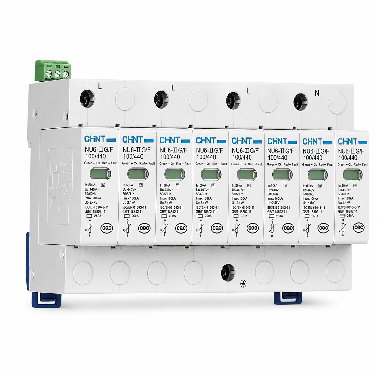
Function and Application
The NU6-ⅡG series surge protective device is suitable for AC 50Hz/60Hz, with a rated voltage of single-phase 230V/three-phase 400V distribution and control systems, meeting SPD II-level testing. It is used to suppress transient overvoltage lower than the equipment's withstand impulse overvoltage and discharge surge energy, thereby protecting the system circuit and equipment. It is suitable for graded coordination with other series surge protective devices to achieve a layered protection system, making the low-voltage distribution system more widely and effectively protected. Complies with standards: GB/T 18802.11, IEC 61643-11, EN 61643-11, and has obtained CQC, CE, and other certifications.
Detailed Description
Parameters:
Maximum Discharge Current: 40kA, 65kA, 100kA
Maximum Continuous Operating Voltage: 255VAC, 275VAC, 320VAC, 385VAC, 440VAC
Rated Discharge Current: 20kA, 30kA, 50kA
Voltage Protection Level: 1.5kV, 1.6kV, 1.8kV, 2.1kV, 2.0kV, 2.2kV, 2.4kV
Poles: 1P, 1P+N, 2P, 3P, 3P+N, 4P
Connecting Wire: ≤16mm²
Short Circuit Current Withstand Capability: 10kA
Remote Signal and Indication: Remote signal function can be selected as needed, the indication function is shown in the product indicator window
Working Status / Fault Indication: Green (Remote signal terminal 11 → 14 normally open, 11 → 12 normally closed) / Red (Remote signal terminal 11 → 14 normally closed, 11 → 12 normally open)
Remote Signal Terminal Wiring Capacity: Maximum 1.5mm²
Remote Signal Contact Switching Capacity: 250V/0.5A; 250V/0.1A; 75V/0.5A
Advantages/Core Functions:
01 High Operating Voltage
The maximum continuous operating voltage can reach 440V
02 Remote Signal Visualization
Remote signal function can be selected, the product indicator window is visualized
03 Complete Poles
Complete 1P~4P poles, meeting different scenarios and customer power needs
Detail Parameters
| Parameter Category | Parameter Item | Parameter Value |
|---|
| Technical Parameter Item | Maximum Discharge Current | 40kA, 65kA, 100kA |
| Maximum Continuous Operating Voltage | 255VAC, 275VAC, 320VAC, 385VAC, 440VAC |
| Rated Discharge Current | 20kA, 30kA, 50kA |
| Voltage Protection Level | 1.5kV, 1.6kV, 1.8kV, 2.1kV, 2.0kV, 2.2kV, 2.4kV |
| Poles | 1P, 1P+N, 2P, 3P, 3P+N, 4P |
| Connecting Wire | ≤16mm² |
| Tightening Torque | 2.0N·m |
| Protection Level | IP20 |
| Dimensions | See Figure 2-Figure 5 |
| Back-up Protection Fuse | See Table 3 |
| Short Circuit Current Withstand Capability | 10kA |
| Transient Overvoltage (TOV) Characteristics | Test under TOV caused by low-voltage system faults | TOV Test Value U1=(t1=5s) |
| | TOV Test Value U1=(t1=120min) |
| Test under TOV caused by high (medium) voltage system faults | Products with combination mode 1P+N and 3P+N: TOV Withstand Mode
Products with combination mode 1P, 2P, 3P, 4P: Not applicable |
| | U1≤275V: TOV Withstand Mode;
U1=320V, 385V, 440V: Not applicable |
| | TOV Fault Mode |
| Communication and Indication | Communication function can be selected as needed, the indication function is shown in the product indication diagram | |
| Working Status/Fault Indication | Green (Remote signal terminal 11 → 14 normally open, 11 → 12 normally closed) / Red (Remote signal terminal 11 → 14 normally closed, 11 → 12 normally open) | |
| Communication Terminal Wiring Capacity | Maximum 1.5mm² | |
| Communication Contact Switching Capacity | 250V/0.5A; 75V/0.5A | 250V/0.1A; 75V/0.5A |