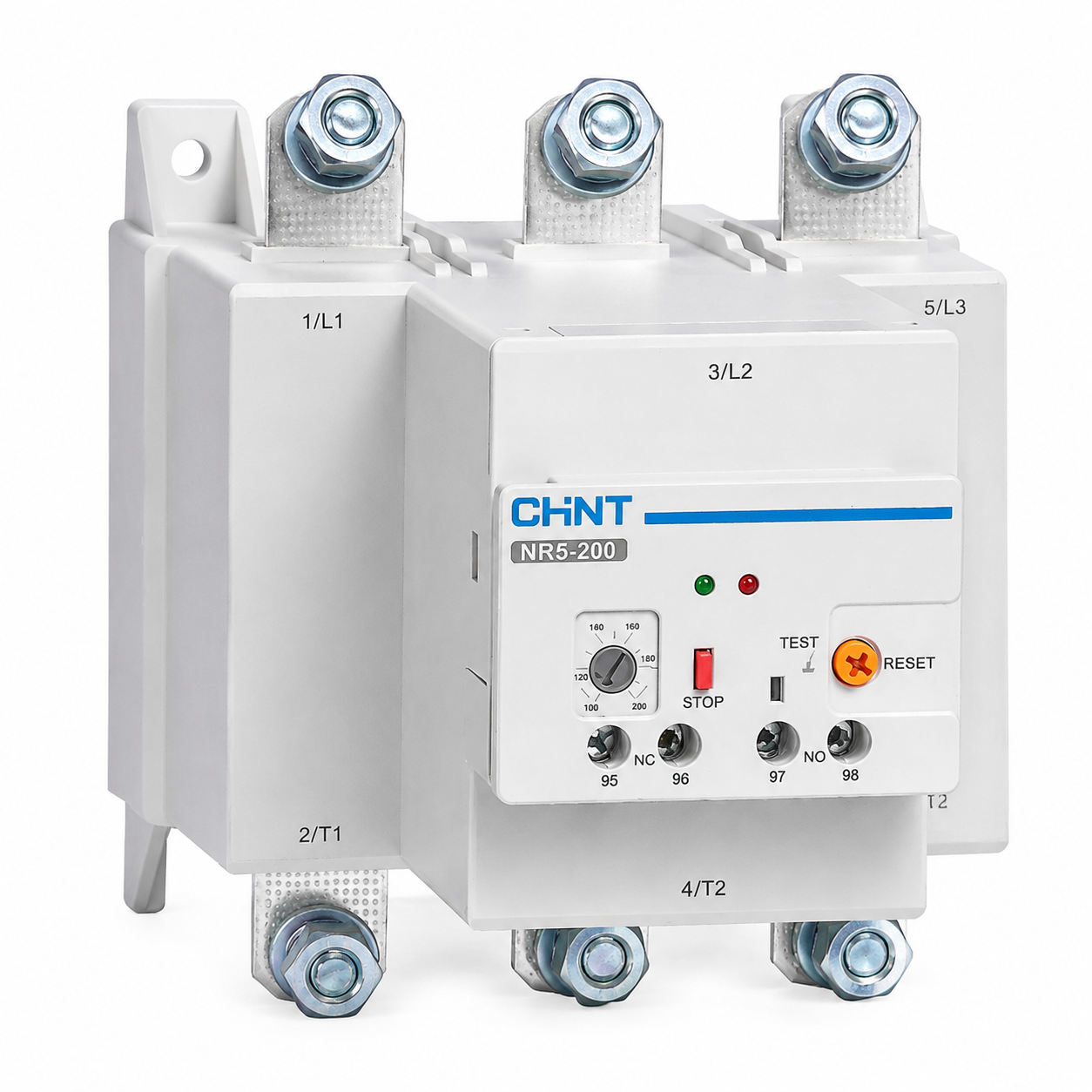
Function and Usage
The NR5 series thermal overload relays are suitable for AC motors with a frequency of 50Hz (or 60Hz), rated operating voltage up to 690V, and working current of 0.1~630A for long-term or intermittent long-term operation. They provide overload and phase failure protection, and also have functions such as temperature compensation, action indication, automatic and manual reset, test and stop function buttons.
Detailed Description
Parameters:
Setting Current Range: 0.1~630A
Tripping Level: 10A
Installation Method: Plug-in Installation, Independent Installation
Frame Current Rating: 25A, 38A, 100A, 200A, 630A
Advantages/Core Functions:
01 Safe and Reliable:
Integrated structure for 100A and above, more robust and reliable
Intelligent manufacturing, automated calibration, ensuring product consistency and reliability
02 Excellent Performance:
Three gold thermal elements, more accurate action
Larger terminal torque, more secure wiring
03 Flexible Application:
Operating temperature -25℃~+55℃, meeting various environmental applications
Electronic structure design, reducing environmental impact
Detail Parameters
| Parameter Category | Parameter Item | Parameter Value |
|---|
| Product Model | NR5-25 | 25 |
| NR5-38 | 38 |
| NR5-100 | 100 |
| NR5-200 | 200 |
| NR5-630 | 630 |
| Rated Voltage Level Ui(V) | 690 |
| Rated Impulse Withstand Voltage Uimp(kV) (Main Circuit) | 8 |
| Enclosure Protection Level | IP20 (Front Side) |
| | IP00 |
| | IP00 |
| Overload Protection | Yes |
| Phase Failure Protection | Yes |
| Manual and Automatic Reset | Yes |
| | Yes |
| | Yes |
| | Manual Reset |
| | Manual Reset |
| Temperature Compensation | Yes |
| Tripping Indicator | Yes |
| Test Button | Yes |
| Stop Button | Yes |
| Installation Method | Insert Type |
| | Insert Type |
| Compatible Mounting Base | MB25-R5 |
| | MB38-R5 |
| | MB100-R5 |
| Rated Setting Current Range (A) | 0.1~25 |
| | 23~38 |
| | 23~100 |
| | 80~200 |
| | 125~630 |
| Rated Working System | Eight-hour Working System, Continuous Working System |
| Auxiliary Circuit | Ith(A) | 5 |
| AC-15 Rated Current (A) 220/230V | 2.7 |
| | 2.7 |
| | 2.7 |
| | 2.7 |
| | 2.7 |
| | 1.5 |
| | 1.5 |
| | 1.5 |
| | 1.5 |
| | 1.5 |
| DC-13 Rated Current (A) 220V | 0.2 |
| | 0.2 |
| | 0.2 |
| | 0.2 |
| | 0.2 |
| Auxiliary Contact Type | 1NO+1NC |
| | 1NO+1NC |
| | 1NO+1NC |
| | 1NO+1NC |
| | 1NO+1NC |
| Compatible Fuse Specification (A) | 6 |
| | 6 |
| | 6 |
| | 6 |
| | 6 |
| Rated Impulse Withstand Voltage Uimp(kV) | 6 |
| | 6 |
| | 6 |
| | 6 |
| | 6 |
| Main Circuit | Wire Cross-sectional Area (mm²) | Single-core or Stranded Wire |
| | Termination Screw |
| | Tightening Torque (N·m) |
| | Single-core or Stranded Wire |
| | Termination Screw |
| | Tightening Torque (N·m) |
| | 1~6 |
| | 4~10 |
| | 4~35 |
| | 25~95 |
| | 50~2X185 |
| | M4 |
| | M4 |
| | M10 |
| | M8 |
| | M10 |
| | 1.7 |
| | 1.7 |
| | 10 |
| | 10 |
| | 20 |
| | 1~2.5 |
| | 1~2.5 |
| | 1~2.5 |
| | 1~2.5 |
| | 1~2.5 |
| | M3.5 |
| | M3.5 |
| | M3.5 |
| | M3.5 |
| | M3.5 |
| | 1.2 |
| | 1.2 |
| | 1.2 |
| | 1.2 |
| | 1.2 |