[Warm reminder] There are too many related models of the product. The prices and parameters marked on the website are for reference only. The specific price for complete sets of customized products shall be subject to call for consultation. New and old customers are welcome to call for consultation!
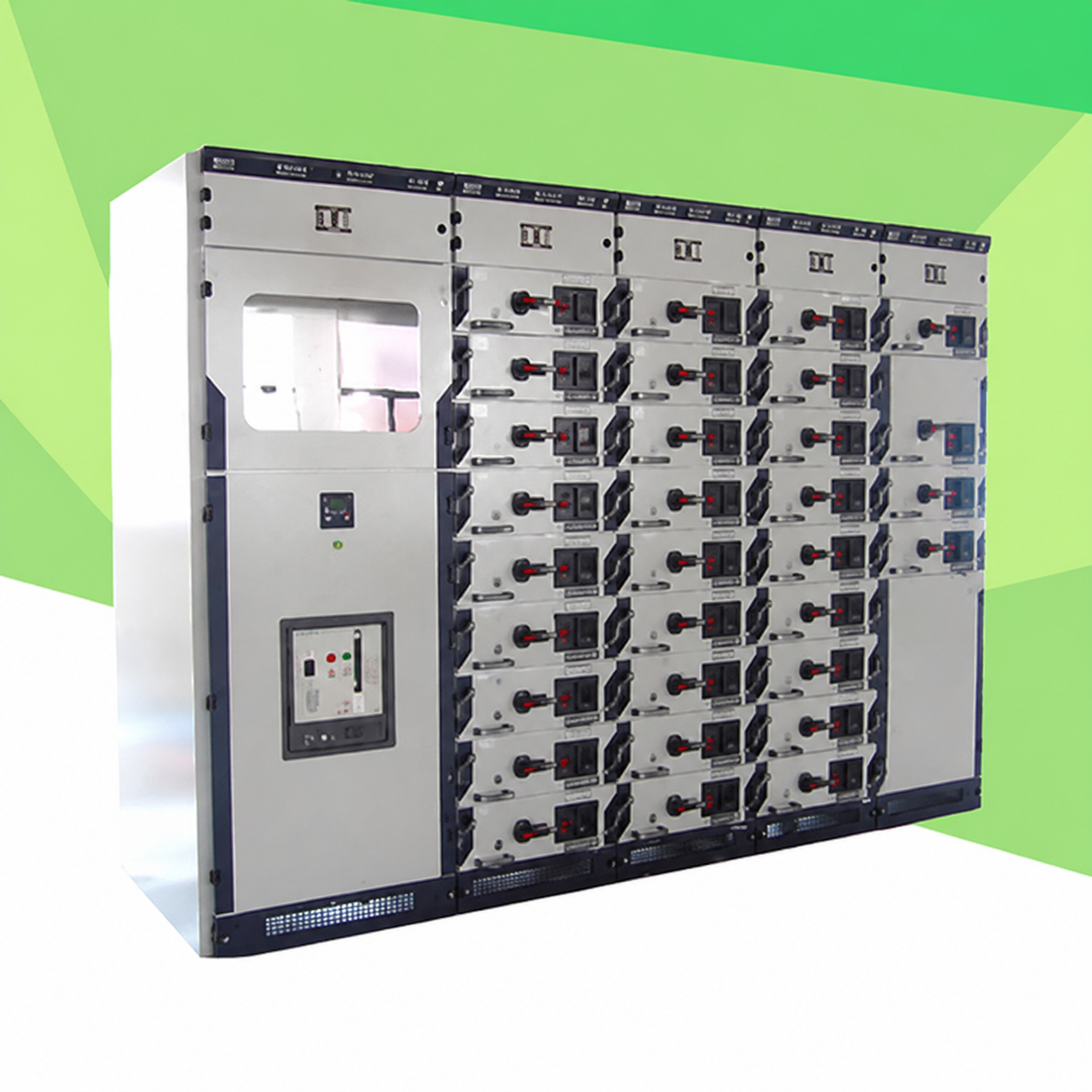
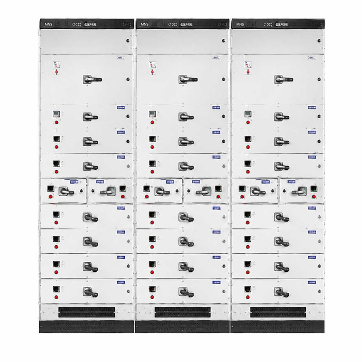
1. Purpose MNS type low-voltage withdrawable switch cabinet is suitable for three-phase four-wire and three-phase five-wire power systems with three-phase AC 50, 60Hz, rated voltage 660V, and rated current below 4000A, as a space between receiving and distributing electric energy. It is widely used in power distribution center PC and motor control center MCC in power plants, substations, factories, mines and high-rise buildings. This product complies with GB725
1. ZBK3600
1. IEC439-1 (1992) standard.
2. Conditions of use 1) The ambient air temperature shall not be higher than +40°C and not lower than -5°C, and the average temperature within 24 hours shall not be higher than +35°C. 2) The relative humidity of the surrounding air should not exceed 50% at a maximum temperature of 40°C. A larger relative humidity is allowed at lower temperatures, such as 90% at +20°C. However, it should be considered that moderate condensation may occasionally occur due to temperature changes. 3) For indoor use, the altitude of the place of use shall not exceed 2000m. 4) It shall be installed in a place without severe vibration and impact and where the electrical components are not subject to undue corrosion. 3 Structural Characteristics The basic frame of the switch cabinet is a modular assembly structure, which is all fastened with screws. Together with doors, partitions, brackets and busbars, drawers and electrical components, it forms a complete switch cabinet with the following characteristics: 3.1 The outer dimensions of the frame and parts and the opening size vary according to the module E = 20mm; 3.2 Since all structural components of the frame are tightly connected with screws, welding deformation and stress are avoided, accuracy is improved, and it has strong versatility, good applicability, and large mechanical strength to meet various performance requirements and changes of the switch cabinet; 3.3 In the MCC scheme, the interior of the switch cabinet is divided into three areas (rooms), the busbar area, the electrical equipment area and the cable area, and the three areas are separated by steel plates to ensure the normal operation of the lines and effectively prevent the expansion of faults. When the drawer is pulled out of the cabinet, no live parts in the cabinet are exposed; 3.4 In the PC scheme, the manual mechanism of the AH and ME circuit breakers protrudes outside the door, and there is no need to open the door panel when operating by hand; 3.5 In the fixed solution, it not only retains the simplicity, practicality, and low price of the fixed solution, but also has the same appearance as a drawer cabinet. The interior is also divided into a busbar area, an electrical equipment area, and a cable area. The three areas are also separated by steel plates or insulation boards. They are safe and reliable. It is an ideal equipment to replace the old domestic fixed products; 3.6 The drawers of MCC cabinets have four standard sizes, which are 200, 300, 400, and 600. They are lightweight in structure, easy to assemble, and have high dimensional accuracy. The four standard sizes can be changed according to the design and user requirements. The drawer unit has good interchangeability, and has a working position and a separation position. The handle can be locked by a padlock at the specified disconnection position; 3.7 This switch cabinet is designed for two power supply types of three-phase four-wire and three-phase five-wire power distribution systems. The neutral bus N wire and the protective grounding bus PE wire are installed on the bottom side of the cabinet, and the outlet ends are connected by bus bars, making it very convenient for users to connect cables; 3.8 In order to ensure reliable continuity of grounding, all common components such as drawer guide rails in the cabinet are galvanized; 3.9 The top of the switch cabinet is equipped with a natural ventilation mesh cover without reducing the protection level of the shell. In short, the switch cabinet adopts a structure that imitates advanced foreign cabinet frames, has high mechanical strength and a high degree of standardization. It conforms to the IEC439 standard and the GB7251 standard as a whole. Its protection level complies with the IP3X in GB4208, and the requirements are equivalent to IP30 in IEC529. 4 Technical parameters Rated operating frequency 50~60 Rated operating voltage (V) 380 Rated insulation voltage (V) 660 Rated operating current of horizontal busbar (A) 630, 1000, 1600, 2500 Rated operating current of pluggable busbar (A) 630, 800, 1000, 1600 Main circuit connector (A) 200, 400 Auxiliary circuit connector (A) 10 Feeding circuit high current (A) 1600 Power receiving current (A) 1000, 1600, 2000, 2500, 3200 Main busbar rated short-time withstand current effective value for 1 second (KA) 30, 50, 80 Main busbar rated short-time withstand current peak value (KA) 6
3. 105, 176 Power frequency withstand voltage for 1 minute (V) 2500 Control motor capacity (KW) 0.5~320 Shell protection level (level) IP30